Visual Circuit Builder
The Visual Circuit Builder is OceanRemote's drag-and-drop tool for designing IoT circuits visually — no coding required.
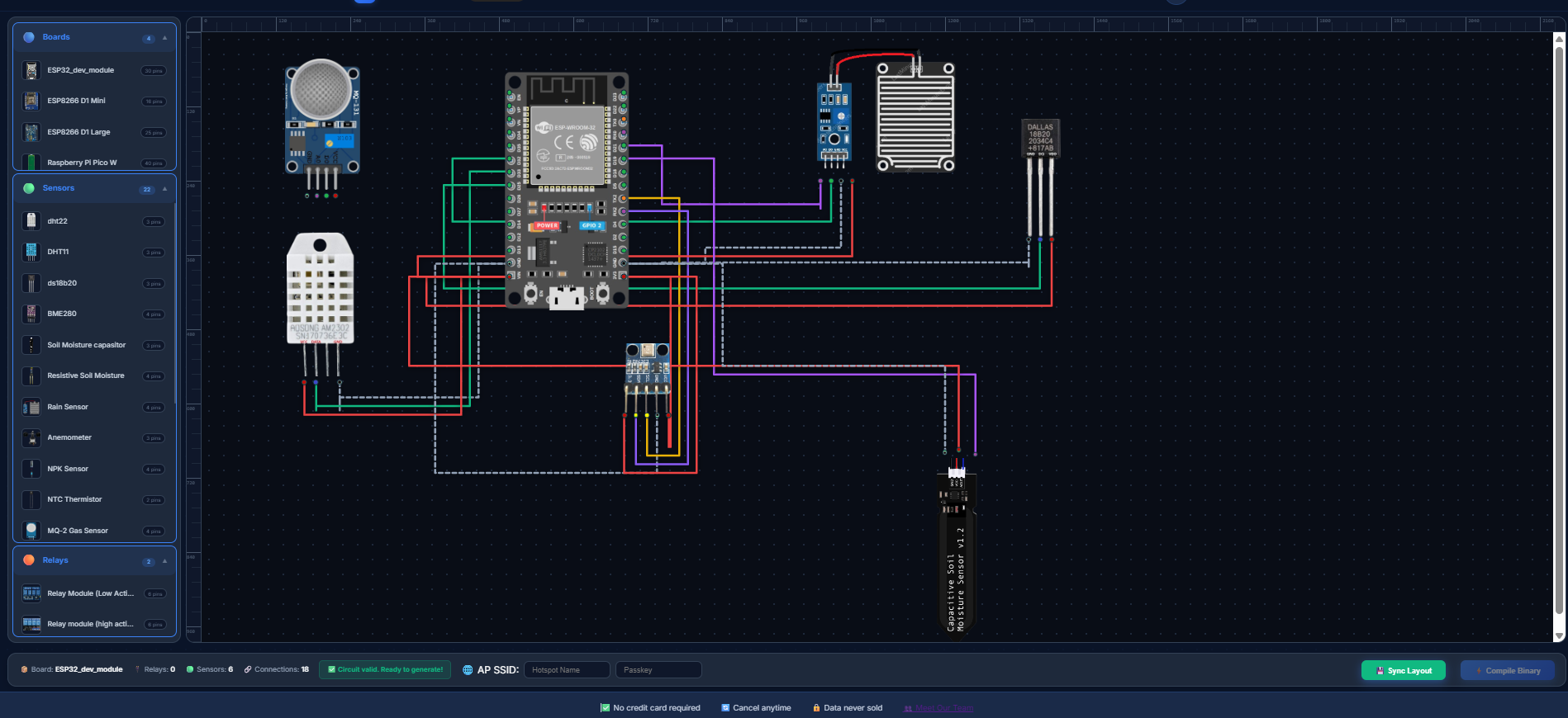
What is the Visual Circuit Builder?
It's a visual design tool that lets you:
- Drag components from a sidebar onto a canvas
- Connect pins by clicking on them
- Generate ready-to-flash firmware instantly
No Arduino code writing needed. Just drag, drop, connect, and compile.
Supported Boards
| Board | WiFi | Analog Pins | Best For |
|---|---|---|---|
| ESP32 | 2.4GHz | 18 | Complex projects |
| ESP8266 D1 Mini | 2.4GHz | 1 | Budget projects |
| ESP8266 D1 Large | 2.4GHz | 1 | Budget projects with more GPIO |
| Raspberry Pi Pico W | 2.4GHz | 3 | MicroPython projects |
Supported Components
The Visual Builder supports 30+ components out of the box:
Temperature Sensors
- DHT22 (Temperature & Humidity)
- DS18B20 (Digital Temperature)
- NTC 10kΩ Thermistor
Environmental Sensors
- Soil Moisture Sensor (x2)
- Rain Sensor
- LDR (Light Sensor)
- BME280 (Temp/Humidity/Pressure)
Gas Sensors
- MQ2 (Gas/Smoke)
- MQ131 (Ozone)
- MQ135 (Air Quality)
Actuators
- Relays (up to 5 per circuit)
- LED
Other Sensors
- Ultrasonic Sensor (HC-SR04)
- PIR Motion Sensor
- NPK Sensor
- TDS Sensor
- pH Sensor
- UV Sensor
- Anemometer
How to Use
Step 1: Select a Board
Drag a board from the sidebar onto the canvas. Only one board per circuit is allowed.
Step 2: Add Components
Drag sensors and relays from the sidebar. You can add up to: - 5 relays per circuit - Unlimited sensors (practical limit: 10-15)
Step 3: Position and Resize
- Drag components to arrange them
- Use the resize handle (bottom-right corner) to adjust size
- Use the rotate button (top-left) to rotate 90°
Step 4: Connect Pins
Click a pin on one component, then click a pin on another to create a wire connection.
Wire Colors:
- Red = VCC (Power)
- Gray = GND (Ground)
- Green = GPIO/Data
- Blue = I2C Data
- Purple = Analog
- Orange = PWM/TX
Step 5: Enter WiFi Credentials
Add your AP SSID and password. This will be embedded in the firmware.
Step 6: Generate Firmware
Click the Compile Binary button. The system validates your circuit and generates Arduino-compatible firmware.
Step 7: Download and Flash
Copy or download the .ino file and upload it to your device using Arduino IDE.
Example: Smart Garden
Here's a typical smart garden circuit:
[ESP32] -> [DHT22] (Temperature/Humidity) -> [Soil Moisture] (x2) -> [Rain Sensor] -> [Relay 1] (Water Pump) -> [Relay 2] (Light)
Keyboard Shortcuts
| Key | Action |
|---|---|
| Delete | Delete selected component |
| Escape | Cancel wire drawing |
Pro Tips
- Rotate components to organize your circuit better
- Rename components for clarity (e.g., "Pump Relay")
- Save your project frequently using the "Sync Layout" button
- Check validation before generating firmware
Troubleshooting
"No board selected"
You must add a board before generating firmware.
"Maximum 5 relays allowed"
The platform limits relays to 5 per circuit.
"WiFi credentials required"
You must enter SSID and password before compiling.
Launch the Visual Builder
Next Steps: Getting Started Guide